Storage and Datacenter Virtualization – Points to Consider
Posted on January 8, 2012 by TheStorageChap in Data Center, Federation, VPLEXIntroduction
As part of an over all strategy to increase IT efficiency, organizations are demanding flexible, agile, fully utilized datacenter infrastructures. This drive for flexibility, agility and improved asset utilization is driving many customers to look at virtualization of the different infrastructure layers within their datacenter:
- Host – Server Virtualization
- Network – Virtual SAN/WAN technologies
- Storage – Storage Virtualization
As part of the drive to increase asset utilization, organizations are also looking at their datacenter strategy, with many customers wishing to move away from an active/passive replication solution – where storage and compute resources remain largely idle at the secondary site, and instead transition to a true active/active datacenter strategy where I/O resources are actively used for production workloads, while at the same time ensuring high availability across datacenters.
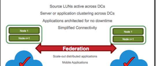
This can be achieved with a combination of storage virtualization and federation.
Storage virtualization provides the transparent mobility and management functionality often used to perform ongoing data migrations between storage arrays. You may also use virtualization to simplify management of multi-storage environments, as well as pool storage across new and older arrays (and extend their useful life).
Distributed federation builds on traditional virtualization by adding the ability to transparently move and relocate data within and across data centers. Federation simplifies multi-array storage management and multi-site information access, allowing capacity to be pooled and efficiently scaled out, on demand, as a set of storage services.
Mobility, Availability and Collaboration
The capabilities of any storage virtualization solution need to be considered from three primary points of view.
- Mobility – Between what resources and locations can I provide data mobility and what is the impact of those data mobility operations?
- Availability – Firstly, the availability of the virtualization architecture itself and secondly, any potential increase in storage or application service availability that it can enable.
- Collaboration – How does the solution aid or enable the aggregation of physical datacenters into a single virtual entity that can enable collaboration across datacenters.
Mobility
Originally the primary use case for storage virtualization, all storage virtualization technologies on the market today enable the non-disruptive movement of virtual volumes across heterogeneous storage arrays, for purposes including:
- Storage array technology refresh
- Redistribution of storage resources to meet changing I/O requirements
- Manual/Automated tiering of data across available storage resources
The majority of storage virtualization solutions have been architected for local site storage virtualization, however a small number of solutions can provide this capability across datacenters, separated over both metropolitan and greater geographic distances.
Points to consider:-
- Support for heterogeneous storage arrays?
- Is non-disruptive mobility possible across I/O Groups or Clusters?
- Performance impact on production application during a mobility job?
- Concurrent number of mobility jobs that can be taking place?
- Can mobility jobs be created and queued?
- Can the mobility job be stopped?
- Is data integrity maintained if a mobility job fails part way through?
Availability
Virtualization Architecture
There are essentially two types of storage virtualization architecture:-
In-band – All read/write IO transitions through the virtualization solution.
Out-of-band – Primary read/write IO transitions between the host and storage. And secondary meta data transitions to the virtualization solution.
All of the primary vendor storage solutions are now based on an In-band virtualization architecture, however there are several ways that In-band storage virtualization can be implemented:
- Within the storage controller
- On commodity servers
- On purpose built hardware
How and where the storage virtualization technology has been implemented can directly impact the over all availability of the solution.
Storage virtualization within the storage controller normally involves the use of write caching, which in turn requires the use of cache mirroring to maintain data integrity in the event of a controller failure. This means that for the majority of virtualization solutions based within the storage array there can only be a maximum of two controllers working against a virtualization IO group, meaning that any failure will result in a single point of failure. It also means that because these controllers are in the array, there is no way to physically separate them across sites or fire-rooms to enable potentially better availability.
The same can be said for the majority of storage virtualization solutions based on commodity server hardware, they also employ write caching and cache mirroring mechanisms meaning that there is a maximum of only two devices participating in an IO group, also resulting in performance degradation and single points of failure in the event of a failure of the virtualization solution . These solutions do however, in some cases, enable the controllers to be split across sites, which we will discuss in a moment.
Solutions purpose built specifically for storage virtualization, tend not to have the same issues. In several cases write caching is not performed at the storage virtualization solution, enabling more appliances or engines to be combined into a single virtualization IO group capable of offering greater availability across multiple failures, potentially greater performance and no restrictions on data mobility.
In the case of local site storage virtualization solutions, the site becomes the potential single point of failure and inline with customer requirements for higher availability; there are several solutions to enable multi-site availability in conjunction with storage virtualization.
Multiple sites with individual local virtualization solutions with active/passive replication between them.
Requires a disruption and in many cases manual intervention to transfer storage and application services to another datacenter. This approach no different to active/passive array replication.

Distributing the components of a local storage virtualization solution across two sites, referred to as a split node configuration.
This method normally results in limited distance between sites, connectivity complexity, as all hosts are dual pathed across datacenters, and only one of the storage assets being actively utilized.

Local virtualization solutions that are federated together to enable virtual volumes that are shared across sites with concurrent read/write access.
This approach enables true active/active storage utilization with all of the availability of a local virtualization solution at each location.

With either a split node or federation type solution it is important to have a cluster witness or quorum resource to avoid any potential ‘split-brain’ scenario in case of a loss on communication between sites. In the majority of cases best practice is to use a third location for the cluster witness or quorum resource. The quorum or cluster witness can range from a number of FC LUNs, requiring FC connectivity between all the sites to a virtual machine requiring only IP access been the primary locations and the third site.
Points to consider:
- Are more than two devices participating in a Cluster or I/O Group?
- What happens if write caching is being used and it has to be switched off due to a failure of one of the virtualization components?
- Can the solution span datacenters?
- What is the maximum distance between sites?
- What are the connectivity requirements between sites?
- What is the quorum device and what physical connectivity is required between the primary sites and the quorum location?
Increasing storage / service availability
All storage virtualization solutions enable the creation of virtual volumes that can be mirrored across multiple physical storage arrays to enable array high availability.
The storage virtualization solutions that are capable of being implemented across sites are also capable of creating virtual volumes that are mirrored across storage arrays, across sites, so that in the event of a localized storage failure, applications can continue accessing the remaining storage in the alternate site. These solutions present a virtual volume that can be accessible to a host in either data center enabling highly available applications to be architected. However there are subtle but important differences in the way that these volumes are exposed and therefore the storage utilized:
Split node configuration
A physical LUN is exposed to all members of the virtualization solution from a storage array at each site. A RAID 1 device is created from these LUNs and a Virtual Volume created from this device. Hosts at either site are dual pathed across the sites. For any host at site A or site B, the virtual volume is accessed through a single preferred node, which is accessing only the primary storage. For example if the preferred node is in Site A and the host in Site B, all traffic would traverse the site links.
Federated virtualization
A physical LUN is exposed from the local storage array in Site A to the local virtualization cluster in site A. A physical LUN is exposed from the local storage array in Site B to the local virtualization cluster in site B. A distributed device is created across the virtualization clusters and a virtual volume created from that device that is accessible across both sites. Hosts in Site A are connected to the virtualization cluster in Site A and hosts in Site B are connected to the virtualization cluster in Site B, however the hosts have concurrent read / write access to the same distributed virtual volume. In this configuration the physical IO is served from the physical storage array local to that site, enabling greater utilization.
Points to consider:
- How are the back-end storage assets utilized across the datacenters?
- How are the front-end virtual volumes accessed across the datacenters?
- What is the impact to application availability of losing a storage array?
- What is the impact to application availability of losing a site?
Collaboration
Collaboration in the context of this topic is the ability to aggregate resources across datacenters to enable shared application services that enable better utilization and better levels of application service availability.
As already discussed there are several methods of enabling virtualization across sites. Collaboration relies on the ability to aggregate datacenters together and enable concurrent read/write access to distributed virtual volumes across those sites. It is therefore important to choose an architecture that can facilitate collaboration across multiple sites and across longer distances.
Collaboration requires support at the OS, application and/or file system layer and it is therefore important that any solution chosen integrates with products such as VMware and Microsoft Hyper V, to enable capabilities such as non-disruptive Virtual Machine mobility to reduce planned downtime, integration into physical and virtual application clustering technologies to enable automated application restart in the event of a site disaster and integration with clustered file system solutions to enable highly available collaborative file systems across sites.
The ultimate aim of collaboration is however to move away from reliance on clustering of applications to enable automated restart and instead utilize the active / active functionality enabled by distributed volumes to create single application instances that run concurrently across datacenters: so that in the event of a site failure, the application simply continues to run at the remaining datacenter locations.
Use cases available today include:
- Clustered file-system solutions that enable collaboration on large datasets that previously would only have been accessible at one location and then would have to be copied to another location for someone else to work on.
- Single database instances concurrently running across datacenters that can remain available even during a datacenter outage.
Points to consider:
- Supported applications and application use cases.
So why EMC VPLEX?
VPLEX addresses the three distinct customer requirements:
- Mobility: The ability to move applications and data across different storage installations—within the same data center, across a campus, or within a geographical region.
- Availability: The ability to create high-availability storage infrastructure across these same varied geographies with unmatched resiliency.
- Collaboration: The ability to provide efficient real-time data collaboration over distance for such “big data” applications as video, geographic/oceanographic research, and others.
Mobility
EMC VPLEX enables the pooling of heterogeneous storage arrays providing seamless data mobility and the ability to manage multiple heterogeneous arrays from a single interface within a data center.
VPLEX Metro and Geo configurations enable migrations and relocations between locations over synchronous/asynchronous distances. In combination with, for example, VPLEX Metro, VMware and Distance vMotion, it allows you to transparently move and relocate Virtual Machines and their corresponding applications and data over synchronous distance. This provides you with the ability to relocate, share and balance infrastructure resources between datacenters.
A VPLEX Cluster is a single virtualization IO group that enables non-disruptive data mobility across the entire cluster. Many virtualization solutions are tied to a pair of nodes and non-disruptive data mobility between I/O Groups is normally disruptive. A VPLEX Cluster supports 8.000 back-end LUNs in the same I/O Group, many virtualization solutions support as little as 1024 back-end LUNs in a single I/O Group and if this is ‘split’ across sites for mirroring and site resiliency there would only be support for half of that number in each site.
When conducting a data mobility job, the additional latency for an application can increase. On average the additional latency during a VPLEX data mobility job is 1-2ms. The additional latency during a data mobility operation for some virtualization solutions can be approximately 8ms, making it often impossible to utilize the application during the ‘non-disruptive’ mobility job.
During a VPLEX Mobility operation any jobs in progress can be paused or stopped without affecting data integrity. Due to the way that some virtualization solutions conduct data mobility an in progress mobility operation cannot be stopped and data integrity will be affected if an array failure occurs for either the source or the target during the mobility operation.
Availability
Virtualization Architecture
Built on a foundation of scalable and highly available processor engines, EMC VPLEX is designed to seamlessly scale from small to large configurations. VPLEX resides between the servers and heterogeneous storage assets, and uses a unique clustering architecture that allows servers at multiple data centers to have read/write access to shared block storage devices.
With a unique scale-up and scale-out architecture, VPLEX advanced data caching and distributed cache coherency provide workload resiliency, automatic sharing, balancing, and failover of storage domains, and enables both local and remote data access with predictable service levels.
Several virtualization solution architectures are based on pairs of appliances to create virtualization I/O Groups. Up to four of these pairs can be managed as a single cluster, however resources such as cache, I/O and ports are only available within the I/O Group. Resources cannot be shared across the I/O Groups.
EMC VPLEX Local and Metro do not perform write caching, only read caching. Therefore the loss of an engine within the cluster would not result in any potential write penalty. Most virtualization solutions do perform write caching, however as an I/O Group in many cases only has two nodes, because of the requirement for cache mirroring, if a node fails write caching would have to be switched off, resulting in less performance than during normal operations.
EMC VPLEX has been architected for multi-site virtualization enabling federation across VPLEX Clusters. VPLEX Metro supports distances of approximately 100KM (max 5ms RTT, FC connectivity) and VPLEX Geo supports distances of approximately 3000KM (max 50ms RTT, IP connectivity). The nature of the architecture will enable more than two sites to be connected in the future.
Multi-site configurations using split-node architecture, where a pair of nodes is split between two data centers are normally no more than 10KM apart and connected over FC. In most cases for this type of configuration inter node and node to back-end disk communication must not cross ISLs and the nodes must be directly connected to the switches with long wave GBICs, resulting in connectivity complexity.
EMC VPLEX uses a Virtual machine located within a separate failure design to provide a cluster witness between VPLEX Clusters that are part of a distributed/federated solution. This third site needs only IP connectivity to the VPLEX sites.
Many solutions require a third site, with a FC LUN acting as the quorum disk. This must be accessible from the virtualization node in each site resulting in additional storage and link costs.
Storage/Service Availability
Each VPLEX site has a local VPLEX Cluster and physical storage and hosts are connected to that VPLEX Cluster only. The VPLEX Clusters themselves are interconnected across the sites to enable federation. A device is taken from each of the VPLEX Clusters to create a distributed virtual volume. Hosts connected in Site A actively use the storage I/O capability of the storage in Site A, Hosts in Site B actively use the storage I/O capability of the storage in Site B.
Split node virtualization solutions require all components to be cross-connected across sites. For example Node A in Site A would need access to the storage in Site A and Site B, likewise for the Node B in Site B. When a virtual LUN is created, it is mirrored across the physical disks, but only one of those disks is the primary for the virtual volume whether it is accessed from Site A or Site B.
VPLEX distributed volumes are available from either VPLEX cluster and have the same LUN and storage identifiers when exposed from each cluster, enabling true concurrent read/write access across sites.
Most split node virtualization solutions have a preferred node, through which all access must be performed, irrespective of if the host is at Site A or Site B.
When using a distributed virtual volume across two VPLEX Clusters, if the storage in one of the sites is lost, all hosts continue to have access to the distributed virtual volume, with no disruption. VPLEX redirects all read/write traffic to the remaining storage at the other site.
Collaboration
VPLEX is the only solution that enables distributed virtual volumes that enable true concurrent read/write access across storage and VPLEX Clusters, across distance. When utilised with application and filesystem clustering technologies it is possible to create highly available and in some cases continuously available applications.
Discussion · No Comments
There are no responses to "Storage and Datacenter Virtualization – Points to Consider".No one has posted a comment on this post yet. Start the discussion!
Leave a Comment